This is part of the series behind the scenes of RP2040 Doom:
- Introduction
- Rendering And Display Composition <- this part
- Making It All Fit In Flash
- Making It Run Fast And Fit in RAM
- Music And Sound
- Network Games
- Development Overview
See here for some nice videos of RP2040 Doom in action. The code is here.
Rendering Introduction
I wanted to drive a VGA signal directly from the RP2040 since VGA is most in spirit with Doom and the ’90s. Driving a VGA signal from the RP2040 really here means driving DPI (16 color pins for RGB 565, a VSYNC pin and an HSYNC pin) and then passing the color pins through resistor DACs. Since driving VGA is more demanding time wise, and uses more RAM than using an external LCD display, aiming for VGA first made most sense.
An easy way to drive VGA video is to use the pico_scanvideo library from the Raspberry Pi
pico_extras repository.
This uses one of the eight PIO state machines to generating timing signals, and another to generate pixel values for
each scanline (in our case 16-bit 5:6:5 RGB).
The timing state machine wakes up the scanline state machine at the start of every display line.
The scanline state machine is fed by DMA from main RAM.
The pico_scanvideo library manages a small pool of scanline buffers, and hands empty ones to the application to be
filled “ahead of the beam”, i.e. just before the scanline needs to be displayed according to the 60fps monitor
refresh.
Thus, with pico_scanvideo, there is actually no need
to have a frame-buffer at all if you can generate all your rendered content fast enough scanline by scanline every
frame.
320x200 is the target resolution to match Doom of the time, however this is likely not a mode
commonly supported by modern displays or TVs. I also don’t have the luxury of tri-linear filtering
to upscale the image smoothly, so if I wanted to upscale it to a higher resolution I needed to use
integer multiples of 320x200. The pico_scanvideo library can do pixel-doubling, tripling etc. at basically no cost;
for horizontal scaling the pixel values are just left on the pins for longer (i.e. clocked out slower) to make the
pixel wider, and for vertical
scaling the same scanline data is repeated for multiple display lines.
To get the closest approximation to the right aspect ratio, I decided to go with 1280x1024 timing (which works out with 4x5 pixels and 2.4 pixels of black above and below the image) along with a 108Mhz pixel clock. This pixel clock is one of the deciding factors in the choice of 270Mhz as the (over)clock for the RP2040.
3D rendering
Back to the rendering; I actually straddled the fence on the “whether to have a frame-buffer” question for a really long time into development. This really comes down to how I planned to draw the 3D game view:
Drawing 3D View Using frame-buffers?
-
I’d need RAM for two frame-buffers for double-buffering.
-
Pixels would be stored as 8-bit palette indexes, matching vanilla Doom’s behavior, as there definitely wouldn’t be enough room for two 320x200x16 frame-buffers (125K each).
-
Scanlines would need to be palette converted to 16 bit by software “ahead of the beam”.
I was still really worried though about the need for 125K total of frame-buffer even in 8-bit, as this basically halves the available RAM.
Drawing 3D View on the fly?
-
For the 3D I would have the game loop generate display-lists of screen-covering (and non overlapping) pixel columns and render from display-lists on the fly at 60fps. Note that Doom itself deals with columns of pixels whether they be wall texture columns, columns of a sprite, or regions where a floor/ceiling needs to be drawn.
-
I prototyped this using two 320x8 “band buffers’ (think old school printer drivers). Because Doom is columnar in its rendering, I’d draw 320 8-pixel-tall columns, overdraw the floors/ceilings within that, and give 8 pixel lines to
pico_scanvideoto display while I moved on to rendering the next 8 pixel band. -
My prototype and calculations showed that I might be able to munge most of the source texture data for any given frame into <64K, and I was hoping to be able to fit that and the metadata needed to manage the columns into less than the size of two frame-buffers. Of course, I’d need to keep source texture data for both current and next frame, along with two frames worth of metadata.
If it worked though, it seemed like it might help with the problem of decompressing textures, since my “cache” of texture columns would be largely reused from frame to frame as much of the scene content remains the same, so i’d probably save a bunch of time there.
I made the following prototype of this on the fly 60fps rendering, running off canned display-lists. It is running concurrently with the music and the game loop:
As promising as this looks, it is using a full 100% of one core for the rendering, and I realized i’d probably actually made some mistakes with my numbers meaning that my column caches might not fit, that the complication factor was immense, and so I figured I’d probably best abandon this whole plan in favor of using double frame-buffers instead.
Column Lists
In the course of prototyping, I had however created an alternate mode of Doom rendering, whereby columns are rendered to display-lists rather than drawn directly to the frame-buffer as in vanilla Doom.
Doom itself is quite good at avoiding overdraw, however given that I knew I would need to decompress textures on the fly every frame, I not only wanted to avoid drawing things which might not be visible, but more importantly to be able to adjust the draw order so that all columns using the same texture (and indeed all screen columns using the same source texture column) could be drawn together, thus decompressing each texture column only once per frame. Creating a list of columns to be displayed that can be sorted by source texture allows this to happen.
Additionally, the generated display-lists cover the entire display and each pixel exactly once. This lack of overdraw allows the rendering to occur in any order, and thus to be more easily split between the two cores.
The size of this column list metadata in RP2040 Doom is 3600 columns at 12 bytes each (i.e. 42K) which is a non-trivial amount of our RAM, however the use of the column lists actually allows us to remove the oft-maligned “visplane” and “drawseg” structures used by vanilla Doom rendering code which are themselves about 70K big.
Unlike vanilla Doom which draws sprites and transparent textures after the scenes is drawn, based on clipping regions saved from earlier rendering, RP2040 Doom records, z-sorts and clips all individual columns (floor, ceilings, walls, sprites) as the scene is drawn.
This does lead to some subtle rendering differences with vanilla Doom, in the “invalid” cases where 2D sprites pass through 3D walls, but the results are not noticeable during game play (at least to me).
Column lists generation
This process happens during the scene (BSP) traversal, which is when vanilla Doom would be rendering walls, ceilings and floors to the frame-buffer as well.
As solid columns are generated, they are allocated a slot in the render_cols array, and inserted into one of 320
linked lists. Each linked list is of non-overlapping columns for each screen x-position, sorted by
y-position. At the
end of rendering, each column is fully covered, as this is vanilla Doom behavior: the entire scene should
always be drawn which avoids the need to clear the screen first.
As mentioned above, depth information for each column is used to clip columns against each other within their list, discarding or splitting as necessary. For performance, the algorithm supports inserting a sorted set of column segments into the sorted list in one pass, which is efficient for sprites or transparent textures, which may generate multiple solid column segments at the same on-screen x-position.
A separate linked list is kept for each x-position for the “fuzzy” (shimmering invisibility) columns, since they behave differently w.r.t. clipping, and the insertion/clipping code path is too hot to be dealing with a bunch of alternative code paths based on the column type.
Rendering to the frame-buffer from the column lists
When the 3D scene has been fully rendered into the column lists, that list is then used to render the screen as soon as one of the frame-buffers is freed up by the display.
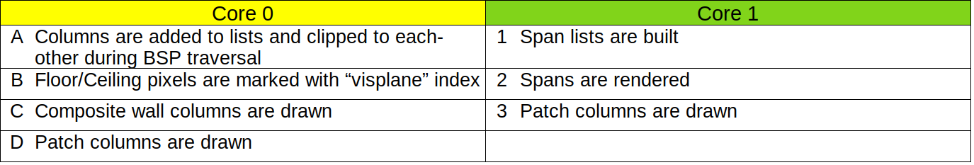
The initial steps of rendering are done on core 0 only:
-
On core 0, all “fuzzy” columns (shimmering invisibility) for each x-position are clipped to the final opaque columns for that x-position. This must be done early, as the regular column display-lists are destroyed during rendering, but the fuzzy columns are not drawn until the end.
-
On core 0, each floor or ceiling column is drawn to the frame-buffer using the color equal to its “visplane” index. The “visplane” index uniquely identifies the floor/ceiling texture used (“flat” in Doom parlance), light level and height in 3D space within the frame. Any horizontal strip of pixels with the same “visplane” index can be drawn in a single, fast rendering operation later.
Note that an extra 9th bit of frame-buffer here is used to disambiguate these “visplane” index values in the frame-buffer from actual rendered pixel values. The floor/ceiling columns are unlinked from their original linked lists at this time, and added to a single “free list” because the freed up space needs to be reused later in the rendering.
Now rendering proceeds with both cores:
-
Core 1 builds new horizontal span lists for each “visplane” index by scanning the 9-bit frame-buffer horizontally for runs marked with the same “visplane” index value. These new “span” list elements are 6 bytes big, and fit two per slot in the old freed up floor/ceiling column entries.
When the scene scan is complete, or the free slot list is exhausted, the gathered horizontal spans are rendered. Since separate span link-lists are kept per “visplane” index, all the spans for one “visplane” index are rendered, then all the spans for the next, etc. This order is additionally optimized such that all the “visplane” indexes that share the same texture (“flat”) are drawn together. This way the 64x64 “flat” texture only has to be decompressed once per frame.
Dealing with all the spans for one flat at a time certainly helps, but additionally, a cache of these decoded flats is kept that grows downward from the top of the 42K display-list area, so that some flat decoding can often be skipped from frame to frame when the number of columns is lower than the max. Flats that are already in the cache are preferentially rendered first to avoid evicting flats from the cache when they are about to be usable.
-
At the same time, core 0 starts rendering “composite” columns. These are texture columns made from more than one source graphic (“patch”) composited on top of each other. Many texture columns have only one patch but these are not considered “composite”. Decoding and rendering these composite columns takes more RAM work area than can be afforded in both cores, so is done exclusively on core 0. Note than unlike in vanilla Doom rendering, the composite column pixels are not calculated until they are actually needed for an onscreen visible column. There is no room to cache them, so this is the cheapest place to do it.
-
As soon as they are done with other work, both core 0 and core 1 continue rendering all the columns for the remaining graphics (patches). These are either sprite columns or single-patch wall columns. Each core just removes a patch from the queue of remaining patches to be drawn, and then renders all the columns for that patch, until the queue is exhausted.
-
Finally, on core 0, any (already clipped) fuzzy columns are drawn over the top of the scene.
This is a movie of vanilla Doom rendering. Yellow is used for all the drawing as it is all performed by a single
thread of execution. The walls, floors and ceilings are drawn during scene (BSP) traversal, then the sprites are drawn
on top. This
would be
true even if they were
clipped by walls closer to the viewer, as vanilla Doom keeps the expensive drawseg structure to record which parts
of which sprites are clipped.
This is a movie of RP2040 Doom rendering of the same scene. This simple scene does not include any fuzzy columns, so these are the pertinent steps:
</svg>
Generating the rest of the display
Thus far, I’ve talked exclusively about the 3D rendering, which in the fixed display layout chosen occupies the top 320x168 of the screen (with the status bar covering the 32 pixels below that).
I realized that I didn’t have enough RAM for the extra 10K per frame-buffer for the last 32 lines, so each frame-buffer is indeed only 320x168 big. So what about the bottom 32 pixels?
Double-Buffered Mode
The only time the full double-buffering is actually used is for the 3D rendered game play, i.e. not during splash or intermission screens. When the 3D view is shown on screen, the status bar is always shown at the bottom, and since there is no backing frame-buffer for it, this has to be drawn “ahead of the beam”.
In the Doom code, the status bar (and the menus etc) are all drawn using rectangular graphics (patches) using V_Patch
functions. I therefore call these graphics “V-patches”. In vanilla Doom, these V_Patch calls draw
the
patches
directly onto a
frame-buffer, however in RP2040 Doom, these functions record the V-patches and their coordinates into
display-lists instead.
A complete V-patch display-list can either then be rendered in 8-bit on top of the current rendering frame-buffer, or it can be passed to the display code as an “overlay” for the next-frame.
In the overlay case, the V-patches will be drawn line by line just ahead of the beam into the scanline buffers as needed. To achieve this, the “overlay” display-list is sorted into a set of V-patches that either start or end on each scanline, and that list is used to maintain a list of active V-patches as the beam works scanline by scanline down the screen. A horizontal strip of each active V-patch is drawn in 16-bit directly into the scanline buffer on top of the just-8-to-16-bit-converted frame-buffer data for that scanline.
In this way the “overlay” V-patch display-list graphics appear in front of the frame-buffer content. In 3D mode the status bar always forms part of the overlay, and since the status bar is always opaque you never notice that there is no frame-buffer behind it!
Note that in double-buffered mode, menus are drawn onto the frame-buffer as part of per-game-frame rendering, as any changes in the menu can be redrawn on the next frame anyway, and it is cheaper than doing the whole menu as an “overlay”.
The whd_gentool used to convert WADs for use by RP2040 Doom, converts V-patches into a custom format suitable for
efficient rendering as horizontal strips, as this needs to be super fast when drawing overlays ahead of the beam at
60fps.
The following movie shows typical double-buffered rendering with the menu showing; the menu is drawn into the frame-buffer, but the status bar is drawn in the overlay. In this example each Doom frame is rendered over the course of two (60fps) display frames although in practice it often only takes one. Note that the overlay display-lists are double-buffered too.
Note that the pause after the display is refreshed every 1/60th of a second represents the vertical retrace/blanking time.
You will also notice that the palette changing effects (e.g. red “blood” when hurt) are not applied until conversion to RGB565 when generating the scanline buffers.
Single-buffered Mode
Some screens, e.g. splash screens, and between level intermissions, are the full 320x200. In this case an individual 320x168 frame-buffer is not large enough, so I use one frame-buffer for the top 168 pixels and the bottom 32 pixels of the other frame-buffer for the rest.
In this mode I cannot double-buffer as there isn’t room for two full copies of the screen. Therefore, menus and any other changing graphics are drawn in the overlay layer (as V-patch display-lists), as their content may need to change, but there is also no off-screen frame-buffer on which to safely redraw.
The follow movie shows an intermission screen with all the foreground changeable content, drawn as overlays via V-Patch display-lists:
Wipe Effect
The wipe effect starts to get tricky, as theoretically you are wiping between two 320x200 screens. Fortunately this is something of an illusion, and with care you can limit the displayed-at-any-time real estate to fall within 168 * 2 pixel heights worth of frame-buffers (which is 1.68 * 200, so just about one and two-thirds times a full screen instead of two).
It is the responsibility of the scanline buffer generation code to select pixels from one of the two screens based on the current wipe offsets, in other words, unlike vanilla Doom, the result of the wipe is never actually realized in a full frame-buffer.
To see how a wipe between two screens is performed using only 1.68 frame-buffers, here is an example of transitioning from one Game A (e.g. demo playback), to a new Game B.
-
We start in double-buffered mode. Game A 3D View is in displayed from frame-buffer 0, Status Bar A is displayed as an overlay.
-
The top of the Game B 3D View is rendered onto the top 136 pixels of frame-buffer 1, Status Bar A is drawn on to the bottom 32 pixels of frame-buffer 1. At this point we are in single-buffered mode using frame-buffer 0 and the bottom of frame-buffer 1 for the last 32 pixels. Note that a wipe is always effectively from one pre-wipe single-buffered screen to another post-wipe single-buffered screen.
-
We can now start wiping between the pre-wipe view and the top of the post-wipe view. At this point we have all 200 pixels of the pre-wipe screen and the top 136 pixels of the post-wipe screen available.
-
About half-way down, the bottom of the Game B 3D View is rendered on to the bottom of frame-buffer 1 as Satus Bar A has now slid off the bottom of the display. At this point we now have the top 168 pixels of the pre-wipe screen and the top 168 pixels of the post-wipe screen available.
-
A little further-down, the Game B Status Bar is drawn onto the bottom of frame-buffer 0 where the bottom 32 pixels of the Game A 3D View (also now off the bottom of the display) used to be. At this point we now have the top 136 pixels of the pre-wipe screen and all 200 pixels of the post-wipe screen available.
-
When we finish the wipe, we are effectively in single-buffered mode using frame-buffer 1 and the bottom of frame-buffer 0 for the last 32 pixels.
-
Finally, we re-enter double-buffer mode, with Game B 3D View displayed from frame-buffer 1 and Status Bar B displayed as an overlay.
Note that the overlay display-lists are mostly empty in this sequence, but would contain V-Patches for the menu if it was displayed during the wipe.
Here is a sped-up version of the above:
Text Mode
Adding a text mode was perhaps overkill in retrospect, but initially I thought I would need it for the network game setup, and it was a nice, fun, brief distraction when I got a bit bogged down in the WAD compression.
Changing display timings on the fly is a bit of a hassle, so I use the same 1280x1024 timing, but this time for a 640x400 mode (80x25 with 8x16 glyphs).
I used an alternate loop in the PIO scanline program to render the raw data at only 2x horizontal pixel stretching,
resulting in 640 horizontal pixels, but dealing with the vertical stretching is more difficult. I really want to
stretch vertically by a factor of 2.5,
however this cannot be
done exactly.
Instead, I
leave pico_scanvideo at 200 logical lines, but take advantage of another of its features to render multiple
actual scanlines within the logical line. One scanline buffer is used for the first 2 timing scanlines, and a different
one is
used
for
the remaining 3, totaling the 5 timing scanlines per logical screen line.
Given the DOS-y font, you would be hard pushed to tell that every other scanline is 0.8x or 1.2x as big as it should be:
Since, I had the text mode, I added a little DOS shell easter egg which is a good way to check the size of your saved games!
End Sequences
When certain levels or the entire game is completed in Doom, special end sequences are shown. These have special rendering code in vanilla Doom, and must also be handled specially in RP2040 Doom.
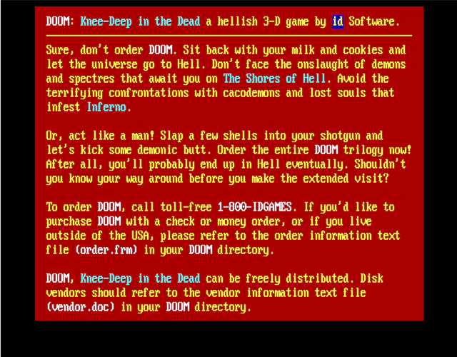
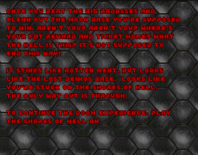
“Typed Message” End Screens
These are single-buffered screens which actually have a single, tiled, floor/ceiling “flat” texture as the background. Since there is a lot of text, and it is not modified once drawn, the text directly is drawn directly onto the single buffer, character by character, as V-patches as the text is “typed”.
“Bunny” End Screen
The end scene of Doom I has a 640x200 image which is slowly scrolled horizontally. I want to treat this just like a regular single-buffered 320x200 screen (with menus and other V-patch overlays), but need to be able to scroll it without tearing. For simplicity, the task of performing the scroll is given to the scanline buffer filling code, which can perform the task at the right time to avoid tearing…
Every time (frame) when the screen must be scrolled, a new one pixel wide
vertical strip of graphic to be
scrolled on is decompressed. This is made available to the display code for the next frame,
and the scanline rendering code for each row memcpys that row of the frame-buffer(s) one pixel to the left, adds the
one new scrolled on pixel for that row, and then converts that strip of 320 8-bit pixels to 16-bit in the new
scanline buffer.
In practice, there are actually two pixel wide strip buffers, because any time data is passed to the display code which is asynchronous with the rest of the game code, double-buffering of some sort must be used.
Note the frame rate indicator in the top right; this is available/toggled in RP2040 Doom by pressing the \ key.
The “THE END” graphics are rendered as V-Patch overlays.
“Doom Cast” End Screen
The Doom II finale shows a cast of characters, with each player and monster type animating over a 320x200 background. This is fine for vanilla Doom because patches are patches as far as it is concerned. In RP2040 Doom however, regular sprites are stored as compressed columnar data, but I need V-patches (stored as horizontal strips) if I want to draw something as an overlay over a single-buffered background.
I didn’t want to be storing all of the (many) sprite frames used in multiple formats in the WAD, so I had to be able to work with our existing compressed, columnar patch data.
Some of these sprites are very big (maxing out at about 257x135) so there is not enough RAM to convert two frames
worth, for double-buffering, into our V-patch format. What I did notice, however, is that 135 is conveniently one less
than
the amount of frame-buffer height left unused in single-buffer mode (the top 168 - 32 = 136 of the second
buffer).
Therefore, the best option is to render the appropriate part of background bitmap to this buffer,
draw the
sprite over the
top, and then memcpy this 320x136 region to the
active frame-buffer soon enough after the VSYNC to avoid tearing.
Fortunately this can reuse majority of the regular sprite->column list->frame-buffer path used by regular rendering
in the game.
The good news is that, whilst simple, this all works like a charm!
Miscellaneous
-
Because I sometimes need to hoist menus from being drawn on the frame-buffer to being drawn via the “overlay” display-lists, I sometimes have to get the game loop to run one more time before the game changes state (e.g. before a wipe).
-
Additionally, during wipes, different parts of the same frame must be drawn at different times, which is a problem, as the column-lists generated by the scene rendering are destroyed during rendering. Therefore, when redrawing a new section of the screen, the code has to back out further into the main Doom code, and re-render the scene from scratch.
-
Much of this code to handle all this is ugly!
-
Rendering of the status bar is extremely time constrained. The background graphic is too large to keep in RAM, but all 5K (320x16x4-bit) of it is needed every frame. The RP2040 has a convenient low priority DMA mechanism to stream data from the flash when XIP accesses are not happening, This is great as it does not pollute the XIP cache, and can happen concurrently with everything else we are doing. However, due to the tight timing and unpredictable nature of the XIP cache usage by other code, this DMA may or may not be complete by the time the pixel values are needed.
Therefore, the rendering for the status bar V-Patch is handled specially, and it works concurrently with the still in progress DMA, stopping when it reaches the end of what has been DMAed, handling the rest normally. In this fashion the status bar scanline is rendered just in time.
Read the next section Making It All Fit In Flash, or go back to the Introduction.
Find me on twitter.